Deployment view
A distribution view assigns software components to specific runtime environments and infrastructure resources. This makes network and operational boundaries visible.
- NodesWhere the artifact runs.
- Data storage devicesCommon condition.
- System boundaryExternal is outside.
Context
Why this is important
Whether a failure or release hits customers depends on where software runs and what it shares. The distribution view maps building blocks to nodes, data storage and external services. The flow of a rollout has its own building block.
This building block describes runtime assignment. C4 ranks system and software levels; Deployment & Rollout handles the controlled version change.
At a glance · Building blocks spread across nodes
Distribution of the modular shop
The modular shop runs as an application on two instances and uses a managed database. The payment connection leads to an external provider.
This is how you read the picture
- Nodes Boxes “Shop instance A” and “Shop instance B” with the same version and configuration.
- Data storage devices Box “shop database” that uses both instances for orders.
- System boundary Box “Payment provider” in the area “External”, connected via “authorize payment”.
Wide diagram · Move laterally if necessary
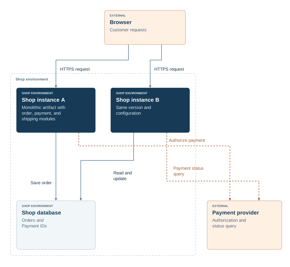
Read diagram as text
- Browser: Customer inquiries (External)
- Shop instance A: Monolithic artifact with order, payment and shipping modules (Shop environment)
- Shop instance B: Same version and configuration (Shop environment)
- Shop database: Orders and payment identification codes (Shop environment)
- Payment provider: Authorisation and status consultation (External)
- Browser → Shop instance A: HTTPS request
- Browser → Shop instance B: HTTPS request
- Shop instance A → Shop database: Save orders
- Shop instance B → Shop database: Reading and modifying orders
- Shop instance A → Payment provider: Authorize payment
- Shop instance B → Payment provider: Request payment status
Benefits & limitations
Helps if:
- Operational handovers and network access approvals benefit from a shared view of nodes and communication paths.
- Availability and recovery planning need actual failure domains and replica placement.
Boundaries
- Two instances in the same zone have limited independence; also assess zones, shared stores and platform services.
- A static view ages with the infrastructure; it is regularly compared against the active configuration.
- It shows placement rather than rollout steps; C4 shows structure, while Recovery covers restoration of service.
In practice
- Identify the environment and version. State the environment, scope and verified configuration. Distinguish the desired state from the topology actually running. This prevents readers from mixing development and production assumptions.
- Show nodes and connections. Map applications, stores, gateways and services to concrete runtime locations. Label communication direction and relevant protocols. This makes network paths and dependencies traceable.
- Check failure domains and redundancy. Mark shared components and assess which failures affect instances simultaneously. Compare the view with recovery assumptions. This shows where redundancy is real and where a bottleneck remains.
Read the detailed explanation
A deployment view shows the nodes on which software and data stores run and how they communicate. It complements structural diagrams such as the C4 model with concrete runtime environments, connections, replicas and infrastructure services. Shared failure domains can then be assessed alongside Recovery requirements.
Scope, environment and the represented state must be clear. Two instances are more independent when they share fewer critical nodes and services. Network protocols and responsibilities support operational handover and review. Comparing the view with the actual deployment configuration keeps it reliable and exposes the running topology and deviations from the target. Redundancy assessment considers shared data and platform services as well as physical separation. The view must give operations and architecture the same picture. Logical software deployment and physical infrastructure may use separate views, connected by a traceable mapping.
Check your understanding
Test yourself in three stages
ReadingCheck in the picture
How many instances of the shop does the view show, and what do they use together?
View the solution with justification
Two instances, A and B. Both access the same shop database.
ApplyingTransferred to a new situation
The shop gets a third instance. What changes in view, what does not?
View the solution with justification
Another node with the same artifact is added; the browser reaches it via HTTPS request, and its edges lead to the shop database and the payment provider. The system boundary and the external provider remain unchanged.
EvaluateWeighing an alternative
Two instances instead of one: what do you win, what does it cost?
View the solution with justification
With two instances, one can be replaced while the other processes orders. For this, both must be compatible with the common database, and the operation becomes more complex.
Explore further
These building blocks continue the thoughts of this page.
References
- C4 – Deployment diagram (opens in new tab)Assigns software instances to the infrastructure of a specific environment.
- arc42 – Deployment View (opens in new tab)Explains infrastructure nodes and the assignment of software components.
- PlantUML – Deployment diagrams (opens in new tab)Shows textual notation for nodes, artifacts, and connections.